Quantcast
Channel: CNCzone.com- Largest Forums for CNC Professional and Hobbyist alike!
Viewing all 73344 articles
Browse latest View live

Need Help! suda1218 engraver machine


Newbie SINGLE START AND DOUBLE START NUT

$
0
0
Hi, I am newbie

I've got problem with my ball screw and nut set I bought from a supplier, I cannot install nut into ball screw, it stuck in the first lap then balls drop.
The screw is 20mm diameter, 10mm lead double start, but the nut has only 1 groove with 1 return, is it single start nut?
Can a single start nut match a double start ball screw in any case ?

Sorry I am not good at English, thank you very much :)

Need Help! T01 can cycle st 0104, Meldas 50

$
0
0
Dears

I have "T01 can cycle st 0104" and this is my problem. On manual mode everything working fine, but when i set MDI mode and press for examply: S500; and press CYCLE START, on display i have error message "t01 can cycle st 0104". The same is when i try to start program from memory. I check all wirles and looks fine. ON PLC Y219 is set 0, propably should be 1
I found propably "X26E PCNT" is set 1 and should be 0. I need to know what is PCNT, and how to turn off. I will be grate full for any help


Best Regards
Pawel
Poland

Newbie SINGLE START AND DOUBLE START NUT

$
0
0
Hi, I am newbie

I've got problem with my ball screw and nut set I bought from a supplier, I cannot install nut into ball screw, it stuck in the first lap then balls drop.
The screw is 20mm diameter, 10mm lead double start, but the nut has only 1 groove with 1 return, is it single start nut?
Is there any case a single start nut can match a double start ball screw?

Sorry I am not good at English, thank you very much :)

Need Help! HITEC TURN 25G won't start up and showing "NC UNREADY"

$
0
0
Dear All,

Hitec turn 25 G won't start up , after system RAM , window RAM, system ROM check, it will do the check for NC status check and then not start and showing only NC UNREADY on the screen
can anyone help
sting

Tool diameter compensation on a Techno CNC machine

$
0
0
Hello guys, first time posting here.

English isn't my first language so I'll try my best.

I was wondering if it is possible to setup (on the CNC software) an offset, or compensation value for the tool diameter.

We are using 0.500'' tools. The fact is that when we get the tools sharpened, the diameter gets smaller as much as 0.475''.

Programs are generated in a program named Microvellum and the tool diameter is set in there.

I would like to be able to change something into the CNC software instead of having to reprogram my jobs everytime I change a tool.

Is it doable with the Techno CVC software (BUILD #400)?

Thanks!

Need Help! Mitsubishi 300V Control

$
0
0
Hi all,
I'm having trouble finding a parameter and service manual for an M300v control.

Any help would be appreciated!

Thanks,

Henry

moesdaddy@charter.net

I need help whit Panasonic software

$
0
0
Good evening everyone, I write these lines to ask for help, I have got two panasonic drivers of the EX series, very old, the driver in particular is the MSD011P1EC03, and the engine is the MSM011PJA, I have got the PDF but not much more, my problem comes in the programming of the driver since according to the instructions there is to do it under MS DOS with the RS232C protocol (besides it does not have neither keyboard nor display), besides it has cost me a lot to find out the scheme of the cable of 6 pins type RJ11 for the communication, I got the oldest version of Panaterm, the 3.70.3, but it does not work with that driver, I've even dedicated a PC just for that with Win XP, but it still does not work, to the maximum that I have arrived is that the Panaterm finds the driver, but by confirming that if I want to communicate with the communication failure and there is no possible way to enter the driver, I have read some post in this forum about this driver so I hope that someone has this program love and want to share it since Panasonic has told me they can not help me beyond Panaterm 3.70.3.

Thank you very much to all

http://www.uppic.es/images/2019/04/16/drivermotor.jpg


New Machine Build Calibration

$
0
0
I've retrofitted a Gerber Sabre with UC300, UB1, Gecko G320X, UCCNC with Nema 44 servo & AMT102 encoder set at 2048 PPR. My UCCNC profile attached.
I am losing position accuracy on each of my axis. By the end of the job they have lost accurate location and hit limit switch when going back to zero.
This is a new build and I've been guessing at my calibration for acceleration, velocity etc.
Any advice how to calibrate for more accuracy?

Attached Images

CNC Construction Set Build 4 Blog

$
0
0
I totally dismantled the CNCCS prototype. Many of the parts are the same as used on the current builds, so I decided to do a new build from scratch so that I could utilize these parts.

On this build I am going to go with aluminum on the plate material. My goal is to do this without any special machining gear. IE pretty much using a drill press.

Before I get started I wanted to show you my layout since you will see much of it in the background of this build.

My shop/lab is divided into six 12" x 12" sections. I label them 1-6 with 1 being the 12x12 section at the double door entrance to my shop.

The section I will be using for this build is section 2 shown here.
_MG_3461.jpg

Currently this shop section contains:
30" shear, break, slip roller
CNCCS Build 3 with downdraft vent and plasma cutter
TIG Welding Workstation
Extra CNC PC
6-Ton Press
20-Ton Press

Attached Images

Need Help! How to copy V26 files to V30?

$
0
0
I recently bought a new laptop.Bought V30 and had it licensed on that computer. Then I had licensed V26 and V27 transferred from old computer to new computer. Tech told me all my old files would come with the transfer. Some did most did not. How can I get these old files on the new computer V30 ?

6 axis control board smoked out a transistor , would need help to understand the prob

$
0
0
Hello guys , i was setting up the Spindle/VFD section of my cnc router table controller https://www.automationtechnologiesin...face-breakout/ and one of the transistor smoked out ....

i am trying to find the real reason why it smoked out before ordering a new one , waiting for delivery , reconnecting and burning a second board....

It ran well for every axis steppers , i made the machine move around no problems , i used the VFD control screen , started , stop , rpm control potentiometer everything was fine . I needed to hook up to the Spindle RPM controller section and understand how to set it up and it burned a transistor .... it hurts !

this transistor with the heatsink burnt


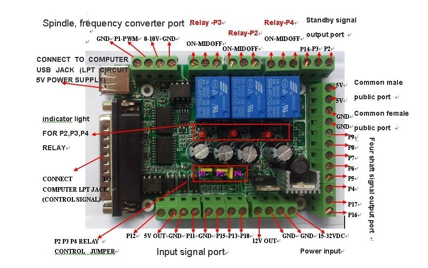
i was really following this pinout plan


Things i did since the last run

- the twisted wires are there to control solenoid air valves who were not set yet , just hooked them up , 2 common grounds and 2 output pins

- i hooked the VFD 10V output pin "VS" and GND to the 0-10V and GND pins of the Spindle section of the BoB , ive read a lot of things on the web and understood it would have been a isolated power supply for the BoB circuit but i think it would be an error i did ....

- i hooked the BoB P1-PWM pin to the "AI" VFD
- on the BoB i used one relay to bridge the VFD common ground to his "X1" pin to turn it ON/OFF thru Mach3 and selected the F1.08 on the VFD screen and didnt try it yet , it started smell burnt 2-3 minutes after the system got powered up ... i was still into Mach3 config

i am wondering if the grounds pins GND on the BoB and "CM" and "GND" on the VFD were actually hooked up together and was bad but i doubt.

i ran to the machine and cut the power because smoking

disconnected the things i just connected to the BoB

tried to power up the system a few minutes after and it got up to smokey smokey and i see the transistor body is cracked ... really trying to understand what is the reason it smoked and wondering the transistor is on which circuit of the BoB , havent found the full board diagram of the BoB ... removed it from the mounting plate, inspected the underside and nothing looked burnt/scarred


Some more images of the build


I have been working on that machine since january , i am really angry of this and hurts !!!

Any ideas ?

Need Help! Left Mach3 in "Offline" over night and can't get G540 out of FAULT mode

$
0
0
Hi,

I was cutting a part for a friend out of AL6061 T6 Aluminum and using a Ball End Mill (1/4 inch) so the cuts where taking a long time. I left Mach3 in "Offline" mode from the "Program Run (Alt-1) screen all night which I do occasionally. When I attempted to put Mach3 in non-Offline mode the next day, the yellow ring around the "Offline" button went off but the Motors did not get power. I checked the 24V power supply and it is outputting 24.1 V. If I turn the off the Charge Pump on G540, it comes out of Fault but the motors will not move and are getting no power.

My Ports and Pins setup is as specified on the G540 Port #1 enabled at 0x03F8 per Com Port Properties.
,X axis: Port 1, Step 3, Direction 2, Y axis: 5, 4, Z axis: 7, 6
Diagnostic screen looks almost stopped, "Time in Int." is moving but "Pulse Frequency is locked at 23258 which is odd. I usually moves around.

As my G540 is in FAULT mode, the Motor outputs are disabled. I changed the G540 to a good G540 and as soon as I enabled "Charge Pump" on the G540, it went into FAULT.
I have attempted a reload of Mach3 to no avail.
Running "Driver Test.exe" states System Excellent (at 75kHz which is what I used before reloading. The graph looks great in DriverTest.exe).
GetPortAddress.exe does not run (maybe it is internal code).

Need the pulse train out of Mach3 to make it to G540 on pin 15 I think.

Please help. I have read everything I can think of and have not found the solution.

Need Help! I screwed up in DI and now my machine won't power up.

$
0
0
Went into DI (diagnostics) because my control was acting weird and not displaying programs correctly from memory. and could not select a program from memory, it was just stuck on that one program and would not even display it correctly using PA. So went into DI mode and I checked most everything. And of course, not having a book or looking online first I screwed up by selecting the START CNC option #2 . That I now have read DO NOT USE. Oh Great.... I couldn't figure out how to exit the DI mode so I thought start cnc would cold start it and get me out. It said power off, wait... power on... not what I expected but Ok,,

Not Good.. So what did START CNC actually do????? I know it killed it.. already..

So my machine is totally dead now and won't even power up when pressing the green button.. I get crap scrolling up on the screen but won't power the axis at all and and won't respond to any inputs.. OK I was stupid,, but now what do I do? Please advise..

Thank you,,
Noyrt

EdingCNC vs Kflop, any advice?

$
0
0
Hi there, I am a maker from Singapore. I am currently looking at either Kflop or EdingCNC to control my machine. Currently it is just a basic 3 axis vertical mill, and I might go for more axis. I am planning to add additive manufacturing capacity into my machine and would like to hear about current user's opinion. I would like to know if I can use Lattepanda Singale Board Computer to run this 2 boards? Thank you.


instructions for auction aquired gages

$
0
0
Good morning. We recently aquired a few gages from auction. Some are Mitutoyo Digital indicator model #ID-F150E, code #543-554-1. I have never had a gage with range and all that and would prefer to be able to look at instructions(because of a personality flaw..haha and time constraint). Thanks for your help.

Face cutting 2 inch carbon steel bar stock

$
0
0
I need to remove 1/4 inch of material from one face of 2 in.² bar stock 16 inches long, 1030 carbon steel

I have a 6 inch diameter 12 tooth carbide face mill Cutter On my Excel VMC with 15 hp spindle motor. It has flood cooling

I have a lot of these parts to machine.

Could somebody more familiar with cutting steel recommend a feed, speed and depth of cut for this job?

Thanks,
Chuck

Need Help! G code for OT A

$
0
0
Hi Guys,
I am the proud owner of an old Colchester CNC2000L lathe with a solid Dickson tool-post i.e. not a turret. And before anybody has a good laugh, its perfect for the work I do because of it's near 1200 mm Z.
I've only just managed to get the control to accept DNC'd files.
My problem now is that the control throws up all sorts of alarms from my CAM generated programs (Autodesk HSM).
I would like some kind person to post me some sample code for the OT A control (preferably with the solid tool post consideration) so I can get the post processor modified to keep the control happy. Or if someone has a proven HSM post for this control, that would be even better. The generic post for Fanuc TURNING on the Autodesk HSM site puts in all sort of codes that it doesn't like, including some milling only codes.
I was told the control doesn't like or doesn't use G54 etc and other sorts of G commands, or indeed a "T" in front of the tool number, so a good program example would be well received. If anyone is sensitive about their part programs being used to make their stuff (very, very unlikely) just knock out important dimensions or sections of irrelevant code.

Any help would be greatly appreciated.

Thanks,
Rathousekid

Need Help! Sizing a servo motor for a 4th (lathe) axis?

$
0
0
I have a small (~100kg / 220lb) 3 axis CNC machine that uses 60W servo motors, and want to add a 4th axis. From what I understand of the machine, it'll probably be easier for me to add another servo motor rather than a stepper.

Without going into lots of detail, the main focus of what I'd want to mill would be a 40cm (16") diameter (hollow) sphere, made from wood. A hollow sphere with a 40cm external diameter and 2cm wall thickness made from very dense wood should weigh around 9kg (20lb).

My machine's realistic cutting capacity is around 120ipm; which equates to about 5cm linear feed per second.

As a 40cm sphere has a maximum outside circumference of ~126cm, it would take about 25 seconds to cut this distance at 5cm per second. This means it'd need to be turned at approximately 2rpm.

Even a small object (5cm diameter; 16cm circumference) would need around 3 seconds to cut around the circumference; which is 20rpm. I.e. I don't need this axis to spin quickly for cutting duties.

Based on https://en.wikipedia.org/wiki/List_o...nts_of_inertia I calculate that my 9kg, 40cm sphere (with a 2cm wall thickness) would have a moment of inertia of approximately 0.212kg.m^2.

Given that torque = moment of inertia x acceleration; if I wanted to accelerate this sphere up to 2rpm (approx 12.6 radians per second) in 1 second I'd need:

0.212 x 12.6 = 2.7Nm

I have a 30W / 6000rpm DC motor that claims to provide 0.2Nm of torque (though I don't have a graph of rpm vs torque so I'm assuming it's not going to provide 0.2Nm of torque at 6000rpm)?

If I were able to reduce this motor by a ratio of 300:1, then ignoring efficiency losses I'd get a maximum of 20rpm, and 60Nm of torque (assuming 0.2Nm at 6000rpm).

Although the items I'm looking at milling will mostly be fairly evenly balanced around the axis, even if I had half of this 9kg ball as a point mass of 4.5kg (44 newtons) at 20cm from the axis, that would be a load of 44 x 0.2m = 9Nm.

Obviously I'm aware there are considerations on the forces of the cutting bit, and the desire for good acceleration for rapids, but are my workings above roughly on the right lines?

I.e. if I had a 30W 6000rpm motor, geared down at 300:1, does it seem reasonable that I'd be able to control and mill the outside of a 40cm diameter, 9kg, wooden sphere?

Newbie Eltee Pulsitron and general sinker EDM questions.

$
0
0
I just bought an Eltee Pulsitron from a retired friend who had an EDM
shop for 30 yrs. Sadly he died last week, before I had a chance to have
him help me with it. I have been around EDM for a decade, but never paid
close enough attention to the setup. So could use all the info/advice
that is available. I own a precision prototype CNC shop, so am pretty
familiar with tool/die work. And have the Eltee running, but not good
enough to add EDM to my shingle yet. I have the book, and a bunch of
spare graphite, electrodes, and 3R holders.

So a whole bunch of basic questions about the Eltee and general sinker EDM:

1. Is there a decent textbook on Sinker EDM? The Eltee book is pretty
good, but it is a little disjointed on the process. Like, set the gap
and gain settings to steady voltage... with a bunch of theory as to
how all the settings are somewhat dynamic... Sometimes the gap/gain
settings make little difference, other-times they make a LOT. Like
to understand why.
2. How do I get it to plunge/retract/plunge? Right now it just plunges
into the material till it gets to the stop depth.
3. How do I determine when the electrode is worn, and time for a new
one? This seems pretty subjective.
4. How can I tell the difference between copper and copper/tungsten? I
have several packs of copper electrode tube. They all look like
copper to me.
5. The book talks about overcut a lot. Is that generally on the ID of
the part?
6. How do I determine spark gap, and how to undersize the electrode? Is
there a rule of thumb, or formula based on amperage/on time?
7. Do all electrode materials use the same spark gap rule?
8. I have the 6-7 pages of electrode/material combinations. Why are
there 7-8 test cuts? Am I supposed to interpolate the settings based
on the test cut parameters?
9. Do any of you have a notebook of material/electrode combinations you
can share? We do a-lot of stainless, and also copper/nickel alloys.
10. What would be a good electrode material for copper/nickel?
11. I called Freedom Tech, and the phone just rings and rings. Since
Frank B. died, is anyone still running the place?
12. How critical is flushing pressure? I am replacing the pressure gauge
with a much narrower range so I can control down to 0.5psi. Do you
normally just set the flushing flow to where you can tell by eye it
is enough?
13. I have the Vectoring head. is it better to just use orbiting to
control fine finishing of ID surfaces? We have a project where we
need to get to 16uin surface finish.
14. How do we determine the best graphite grades to use? I understand
grain size, etc.. but This seems like black magic along with most of
the Sinker process.
15. How do we use the capacitor bank switches to improve finishes?
16. Do you have a fume hood above the sinker to capture the smoke/fumes?
I have never been there during heavy roughing jobs, so no idea if
lots of smoke is normal, or we just had the tank/fluid level too
low. We were aggressively roughing some aluminum and there was
copious smoke.
17. We need to cut a very small 90° tapered seat (In copper/nickel).
Also with a 16uin finish. Is it best to orbit that cut, and use the
slurry to get us that finish? Or are we better off machining that
feature conventionally using a chamfering tool on a VMC?
18. How do I know when dielectric is going bad?
19. On the Eltee, the fill valve never closes off the tank flow
completely. Is that normal, or is there a bad seal (O-ring) in the
valve manifold? \
20. The Vacuum line seems to always pull a low vacuum. Is that a bad
seal? Or Normal? We have the vacuum ball valve in the tank set to
halfway like the book says.
21. The tank catch tray does not drain very well. Is that normal? Should
I plumb the catch tray into the vacuum line?
22. Does the Futaba DRO have decent battery backup? I'd like to leave
the origin sets in the DRO, so I don't have to re-indicate at each
power-on.
23. Lastly, we have a very challenging internal o-ring undercut project
that comes back once a year or so, in Inconel 718. For a -004 o-ring
groove. So the electrodes are VERY fragile. Could use some sage
advice for that. We currently use a great EDM shop for that feature,
but hope to bring the operation in-house to help pay for this machine.

Viewing all 73344 articles
Browse latest View live


<script src="https://jsc.adskeeper.com/r/s/rssing.com.1596347.js" async> </script>